EXACT Turbofan LH2 Hybrid

D250-TFLH2-MHEP-2040

Key Characteristics

Research Category
Future Concept
Entry into Service
2040
Passengers
250
Range
2778 km
Wing Span
42 m
Maximum Take-Off Mass
82.7 t
Cruise Mach Number
0.78
Cruise Speed
832.7 km/h
Energy Carrier
LH2
Energy Consumption
13.6 kWh/pax/100 km
Total Installed Power
41.6 MW

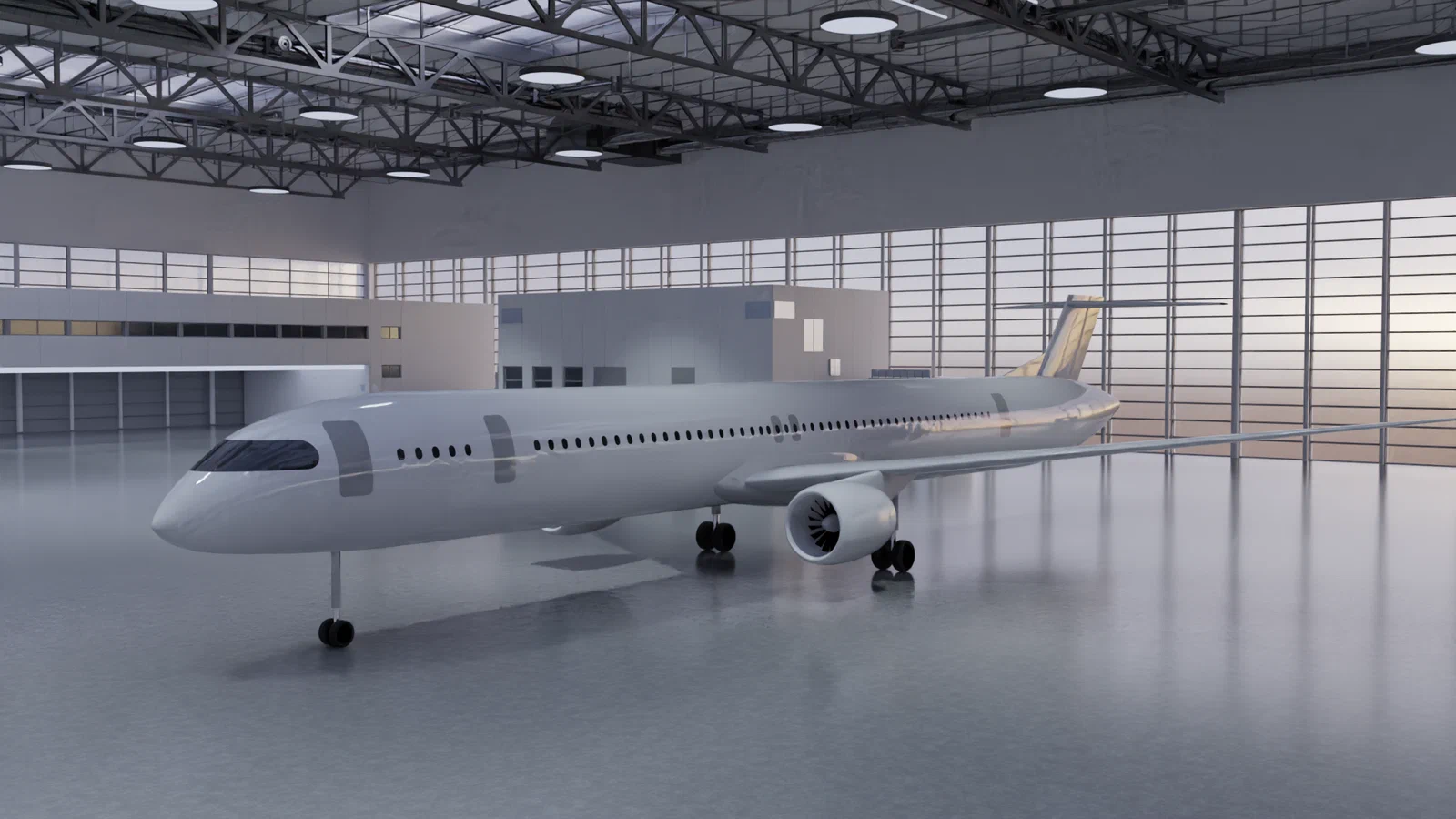
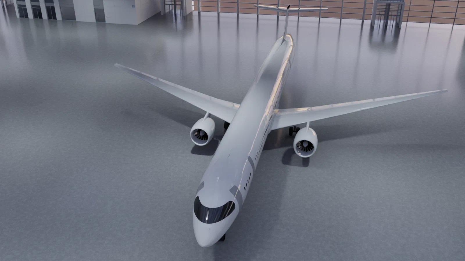
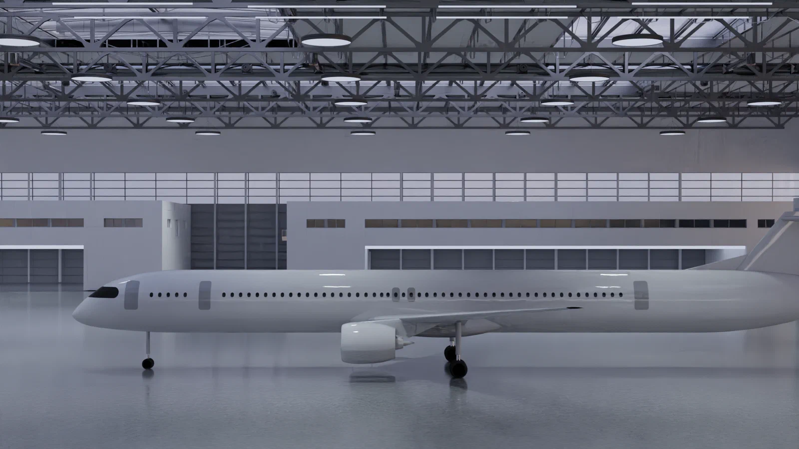
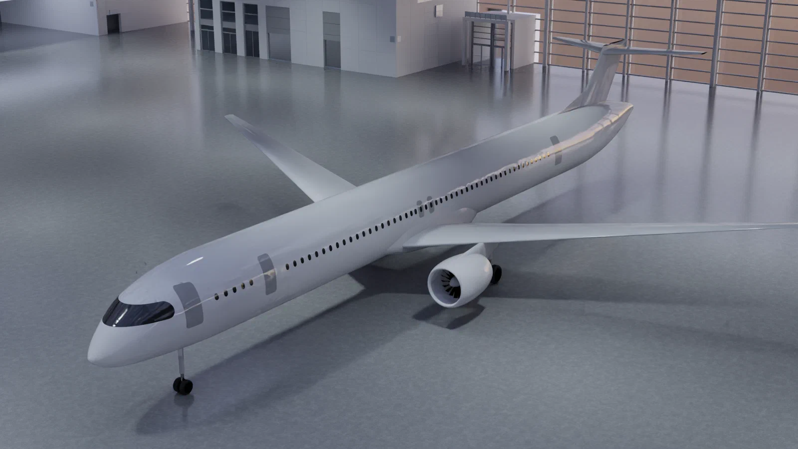
The D250-TFLH2-MHEP-2040 is an innovative short-range aircraft. Developed for entry into service in 2040, the aircraft features the use of liquid hydrogen (LH2) as an energy source to power a Mild Hybrid Electric Propulsion (MHEP) system.

This system combines two gas turbines with fuel cells, allowing more efficient use of fuel, particularly on shorter flights. This reduces energy consumption and improves sustainability.

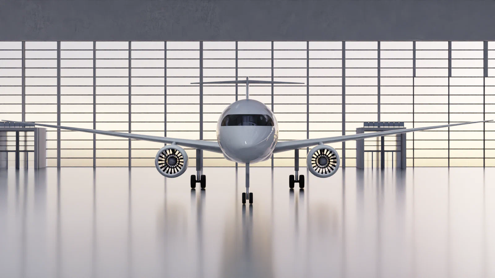
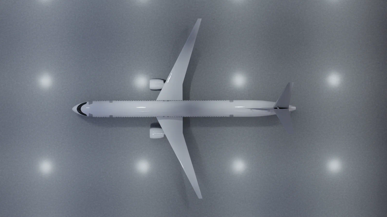
It is powered by liquid hydrogen (LH2), providing a clean energy alternative that supports the sustainable operation of the aircraft. To improve aerodynamic performance, the design incorporates foldable wingtips, allowing greater efficiency while still fitting within the 36-metre gate limit at airports. The carbon fibre reinforced polymer (CFRP) wing structure reduces the weight of the wings, improving overall performance and efficiency.In addition to these technologies, the aircraft uses an all-electric on-board system architecture, further boosting energy efficiency. The design range is shorter than that of many current short-haul aircraft, at 2800 kilometres, balancing energy consumption while still covering over 85% of the short-haul market.

This aircraft concept represents a significant step towards the future of aviation, combining novel- technologies with a focus on sustainability, efficiency, and the ability to meet future market needs.

The most important differences to today’s short-haul aircraft are:

  1. Mild-Hybrid-Electric-Propulsion (MHEP) architecture consisting of two gas-turbines and fuel-cells instead of a conventional gas-turbine propulsion
  2. Liquid hydrogen (LH2) as main energy carrier
  3. Foldable wingtips to increase the aerodynamic efficiency
  4. Reduced wing mass and higher wing-spa through carbon fiber reinforced polymer (CFRP) wing structure instead of aluminum
  5. All-electric on-board system architecture
  6. Reduced energy consumption at comparable missions through shorter design-range (from 2800 kilometres to approximately 4600 kilometres) while still covering most of the short-range market (>85%)
  7. Reduced energy consumption per passenger by an increased passenger capacity

Advantages

  • High climate impact reduction potential
  • Potentially economically advantageous compared to aircraft operated with synthetic kerosene
  • Low primary green electric energy requirements
  • Less energy consumption at the majority of missions (short distances below 1000 kilometres) compared to an LH2 powered aircraft without the MHEP-system
  • The combination of this design range (2,800 kilometres) and design passenger capacity (250) is the sweet spot for single-aisle short-range hydrogen aircraft in terms of energy efficiency. Longer design ranges would require more tank volume and therefore longer fuselages, reducing efficiency for the more relevant shorter missions. There would also be significant challenges in terms of landing gear integration and fuselage structure. A possible solution would be to switch to a twin-aisle configuration, which would further increase fuel consumption. In general, the definition of the design mission, which defines the available range flexibility and the most relevant operational missions (usually much shorter), is more sensitive for LH2 compared to kerosene powered aircraft.

Challenges

  • Global implementation of LH2 might be challenging
  • Rather high uncertainties of the cryogenic storage and processing systems in mass, volume, production costs, maintenance efforts and lifetime
  • Economically challenging if LH2 costs not sufficiently low compared to sustainable aviation fuel. One of the rare major advantages of LH2 compared to SAF are the lower energy carrier production costs. In case LH2 is just slightly cheaper than SAF, the economical drawbacks of other costs are more dominant.
  • The integration of the MHEP-system could be associated with risks

Project & Partners

The aircraft was designed in the DLR-project EXACT as one of the most promising future aircraft concepts with the potential to reduce climate impact drastically while being economically viable. It was designed to enter into service in 2040.

Outlook

The detailed integration of the MHEP system into the aircraft and the electric motors in the gas turbine will be studied in detail in future. Furthermore, synergies with the on-board systems as well as advantages in gas turbine design should be investigated in detail.

Key Characteristics

Mission and requirements

Design Range
1500 (2778) NM (km)
Design Passenger Capacity
250
Design Cruise Mach Number
0.78
Entry into Service Year
2040
Distance to alternate Airport
200 NM
Loiter Time
30 min
Contingency
3%

Performance

Take-off-Field-Length
1900 m
Approach Speed
140 kts (CAS)
Max Operating Altitude
41000 ft
Min. Climb Rate
300 ft/min

Masses

Max. Take-Off Mass (MTOM)
82.7 t
Operating Empty Mass (OEM)
55.4 t
Max. Landing Mass
81.5 t
Maximum Fuel Mass
3.6 t
Max. Payload
25 t

Geometry and cabin

Wing Span (unfolded)
42.0 m
Wing Span (folded)
36.0 m
Passenger Seats Abreast
6

Propulsion and energy

Propulsion Architecture
MHEP (Turbofan / Fuel-Cell)
Energy Carrier
Liquid Hydrogen

Energy consumption

Block-Energy (@ Design Mission)
312.9 GJ
Block-Energy (@ Evaluation Mission, 500NM)
125.4 GJ
Block-Energy per Pax and NM (@ Design Mission, high density)
0.834 MJ/PAX/NM
Block-Energy per Pax and NM (@ Evaluation Mission, high density)
1.003 MJ/PAX/NM

Mass Breakdown

Share of the maximum take-off mass (MTOM 82.7 t)
Fuselage Structure 16.9 % · 14.00 t
System 11.7 % · 9.68 t
Wing 10.9 % · 8.97 t
Engine 8.1 % · 6.72 t
OIM 8.0 % · 6.64 t
Furnishing 4.8 % · 3.99 t
Landing Gear 3.8 % · 3.16 t
Pylon 1.1 % · 0.91 t
VTP 0.8 % · 0.69 t
HTP 0.8 % · 0.62 t
Fuel Block 3.2 % · 2.61 t
Fuel Reserve 1.2 % · 0.95 t
PAX 28.7 % · 23.76 t
Cargo 0.0 % · 0.00 t

Payload-Range Diagram

Payload over range
Payload-range limit Study missions
Show data as table
PointRange (NM)Range (km)Payload (t)
Limit0025.00
Limit7111,31625.00
Limit1,5002,77823.75
Limit2,0913,8720.00
Study mission15027823.75
Study mission30055623.75
Study mission50092623.75
Study mission8001,48223.75
Study mission1,2002,22223.75
Study mission1,5002,77823.75

Technical background information

The Mild-Hybrid-Electric-Propulsion (MHEP) Architecture

The MHEP system consists of two turbofan engines for main power and polymer exchange membrane (PEM) fuel cells for off-design operation, both powered by LH2. The idea is to replace the gas turbine power with the fuel cell during low-power and off-design phases (taxiing, descent). In order to be able to fly these phases on fuel cell power alone, the on-board system must also be powered by the fuel cell. The gas turbine achieves high efficiencies at high power levels and high power settings, as well as high gravimetric power densities. The fuel cell, on the other hand, provides high efficiencies also at low power levels and especially at low power settings, but has rather low power densities. The MHEP architecture combines the advantages of these two power sources and reduces energy consumption, especially for shorter missions.
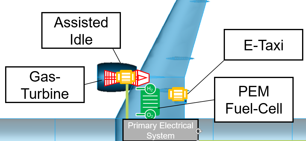
EXACT Turbofan LH2 Hybrid – propulsionArchitecture

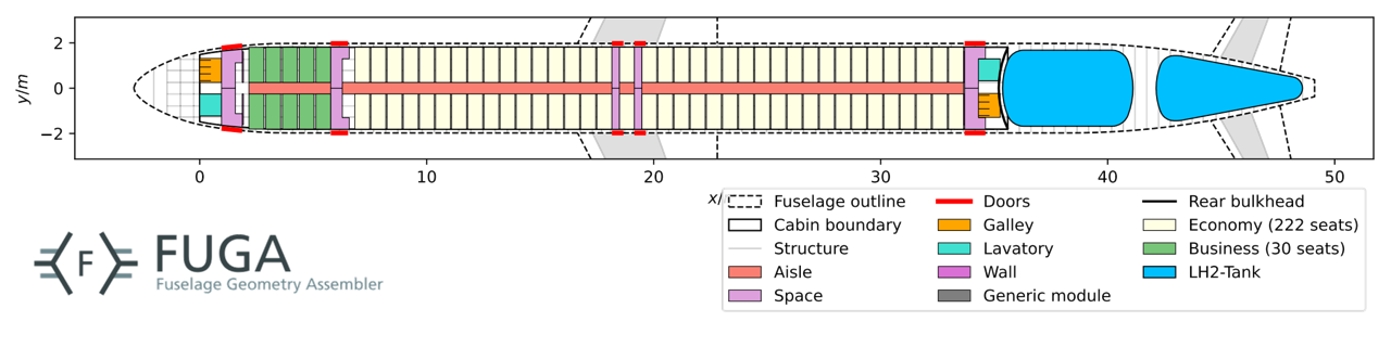
Cabin layout

EXACT Turbofan LH2 Hybrid – cab_lopa

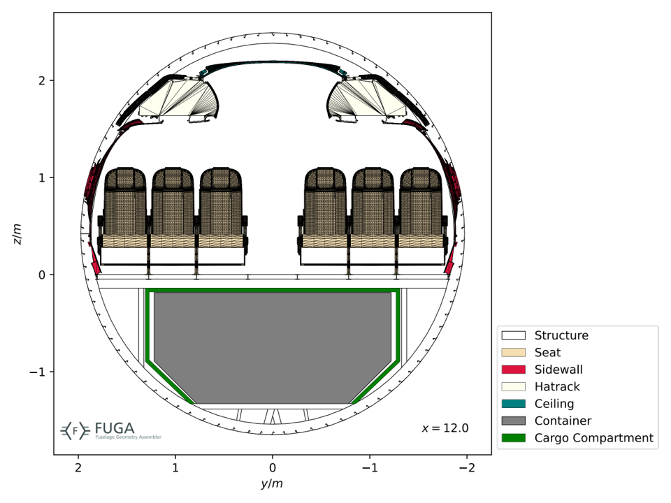
Cabin cross-section

EXACT Turbofan LH2 Hybrid – cab_section